西门子代理商 6ES72883AQ040AA0
西门子代理商 6ES72883AQ040AA0
西门子代理商 6ES72883AQ040AA0
SIMATIC S7-200 SMART, 模拟输出 SM AQ04,4 AO, +/-10V,11 Bit 分辨率, 或 4-20mA,11 Bit 分辨率
_______________________
SIEMENS(西门子销售中心)
上海朕锌电气设备有限公司
zx-plc.com )
联系人:万紫云(销售经理)
手 机:(微信同步)
Q Q:27798 23058 zx-plc.com )
座 机:
______________________________________
(SIEMENS) 诚信走天下,走遍天下有朋友;上海朕锌电气设备有限公司是一家从事西门子工业自动化产品和数控系统销售、技术服务及培训的工程服务公司。
销售代理西门子WINCC组态软件,西门子PLC编程软件,西门子PLC,S7-200CN/S7-200/S7-300/S7-400/S7-1200/(6ES7/6GK/6AV/6FC/6SN/6FX/6SE/6RA/6DD/7ML/7MH/7KM/7MF/3RV/3RH/3TF)西门子PROFIBUS-DP总线,RS485总线接头,CP网卡,变频器,触摸屏,低压电器,数控伺服备件

line; white-space: normal; orphans: 2; widows: 2; font-stretch: inherit; background-color: rgb(255, 255, 255); font-variant-ligatures: normal; font-variant-caps: normal; -webkit-text-stroke-width: 0px; text-decoration-style: initial; text-decoration-color: initial;">系统电源 (PS)
系统电源为背板总线提供内部所需的系统电压。这种系统电压将为模块电子元件和 LED 指示灯供电。 CPU (以及PROFIBUS CMs和以太网CPs, PtP-CMs ) 或者接口模块未连接到 24 VDC 负载电流电源时,系统电源还可以为其供电。
line; white-space: normal; orphans: 2; widows: 2; font-stretch: inherit; background-color: rgb(255, 255, 255); font-variant-ligatures: normal; font-variant-caps: normal; -webkit-text-stroke-width: 0px; text-decoration-style: initial; text-decoration-color: initial;">负载电源 (PM)
负载电流电源未连接到背板总线,给模板的输入输出回路供电。此外,可以根据需要使用负载电源为 CPU 和系统电源提供 24 VDC 电压。
line; white-space: normal; orphans: 2; widows: 2; font-stretch: inherit; background-color: rgb(255, 255, 255); font-variant-ligatures: normal; font-variant-caps: normal; -webkit-text-stroke-width: 0px; text-decoration-style: initial; text-decoration-color: initial;">在这种情况下可以为每个CPU组态多8个输入/输出模块。但是需要在 STEP7 (TIA Portal) 中确认电源容量是否够用,例如对 CPs 和 CMs,需要额外再加电源。
line; white-space: normal; orphans: 2; widows: 2; font-stretch: inherit; background-color: rgb(255, 255, 255); font-variant-ligatures: normal; font-variant-caps: normal; -webkit-text-stroke-width: 0px; text-decoration-style: initial; text-decoration-color: initial;">下面的三个表格给出了为模板供电的可能配置方式。
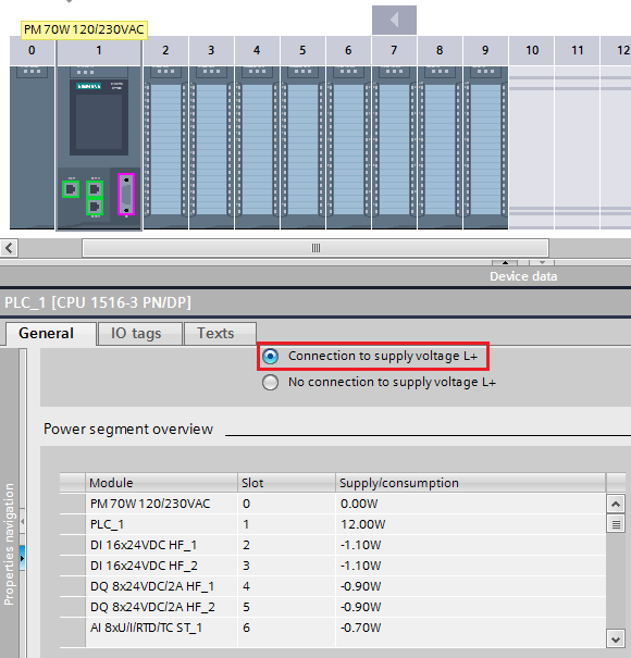
只通过 CPU 给背板总线供电
通过负载电源向 CPU 提供 24 VDC 电压。CPU 的参数分配: STEP 7 的“常规”(General) 选项卡内“属性”(Properties navigation) 区域导航中,选择“连接电源电压 L+” (Connection to supply voltage L+) 选项,以便 STEP 7 可以正确进行供电平衡计算。
| CPU | 系统电源 | 提供给模块的 电源容量 [W] | ||
| 简称 | 订货号 | 简称 | 订货号 | |
| 1511-1 PN | 6ES7511-1AK00-0AB0 | - | - | 10 |
| 1513-1 PN | 6ES7513-1AL00-0AB0 | - | - | 10 |
| 1516-3 PN/DP | 6ES7516-3AN00-0AB0 | - | - | 12 |
表 01
line; white-space: normal; orphans: 2; widows: 2; font-stretch: inherit; background-color: rgb(255, 255, 255); font-variant-ligatures: normal; font-variant-caps: normal; -webkit-text-stroke-width: 0px; text-decoration-style: initial; text-decoration-color: initial;">
图.01
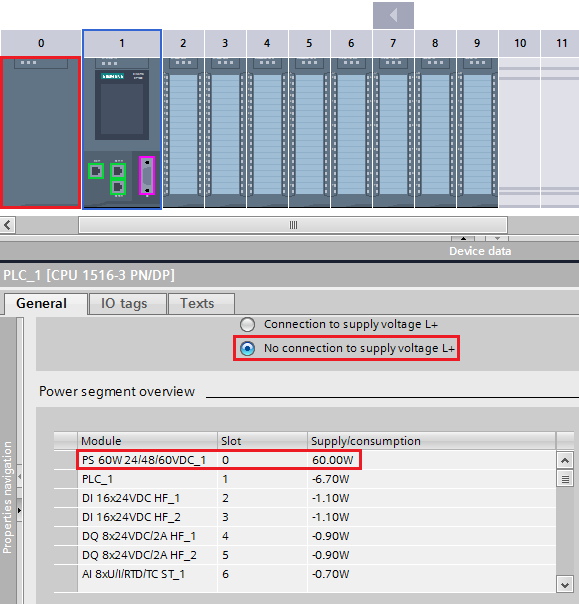
只通过系统电源给背板总线供电
位于 CPU 左侧 0 号槽的系统电源通过背板总线为 CPU 供电。CPU 的参数分配:在 STEP 7 的“常规”(General) 选项卡内“属性”(Properties navigation) 区域导航中,选择“未连接电源电压 L+”(No connection to supply voltage L+) 选项,以便 STEP 7 可以正确进行供电平衡计算。
| CPU | 系统电源 | 提供给模块的 电源容量 [W] | ||
| 简称 | 订货号 | 简称 | 订货号 | |
| 1511-1 PN | 6ES7511-1AK00-0AB0 | PS 25W, 24V DC | 6ES7505-0KA00-0AB0 | 19,5 |
| 1511-1 PN | 6ES7511-1AK00-0AB0 | PS 60W, 24/48/60V DC | 6ES7505-0RA00-0AB0 | 54,5 |
| 1511-1 PN | 6ES7511-1AK00-0AB0 | PS 60W, 120/230V AC/DC | 6ES7507-0RA00-0AB0 | 54,5 |
| 1513-1 PN | 6ES7513-1AL00-0AB0 | PS 25W, 24V DC | 6ES7505-0KA00-0AB0 | 19,5 |
| 1513-1 PN | 6ES7513-1AL00-0AB0 | PS 60W, 24/48/60V DC | 6ES7505-0RA00-0AB0 | 54,5 |
| 1513-1 PN | 6ES7513-1AL00-0AB0 | PS 60W, 120/230V AC/DC | 6ES7507-0RA00-0AB0 | 54,5 |
| 1516-3 PN/DP | 6ES7516-3AN00-0AB0 | PS 25W, 24V DC | 6ES7505-0KA00-0AB0 | 18,3 |
| 1516-3 PN/DP | 6ES7516-3AN00-0AB0 | PS 60W, 24/48/60V DC | 6ES7505-0RA00-0AB0 | 53,3 |
| 1516-3 PN/DP | 6ES7516-3AN00-0AB0 | PS 60W, 120/230V AC/DC | 6ES7507-0RA00-0AB0 | 53,3 |
表 02
line; white-space: normal; orphans: 2; widows: 2; font-stretch: inherit; background-color: rgb(255, 255, 255); font-variant-ligatures: normal; font-variant-caps: normal; -webkit-text-stroke-width: 0px; text-decoration-style: initial; text-decoration-color: initial;">
图 02
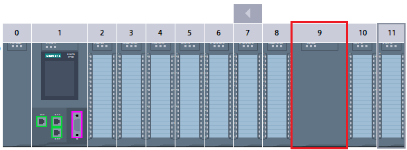
通过 CPU 和系统电源给背板总线供电
向系统电源提供允许的电源电压,并通过负载电流电源向 CPU 提供 24 VDC 电压。CPU 的参数分配同条。在 CPU 右侧的插槽中,多插入 2 个系统电源(电源段)。
系统电源 | 提供给模块的 电源容量 [W] | |
| 简称 | 订货号 | |
| PS 25W, 24V DC | 6ES7505-0KA00-0AB0 | 25 |
| PS 60W, 24/48/60V DC | 6ES7505-0RA00-0AB0 | 60 |
| PS 60W, 120/230V AC/DC | 6ES7507-0RA00-0AB0 | 60 |
表 03
line; white-space: normal; orphans: 2; widows: 2; font-stretch: inherit; background-color: rgb(255, 255, 255); font-variant-ligatures: normal; font-variant-caps: normal; -webkit-text-stroke-width: 0px; text-decoration-style: initial; text-decoration-color: initial;">
图 03
line; white-space: normal; orphans: 2; widows: 2; font-stretch: inherit; background-color: rgb(255, 255, 255); font-variant-ligatures: normal; font-variant-caps: normal; -webkit-text-stroke-width: 0px; text-decoration-style: initial; text-decoration-color: initial;">关于系统电源和负载电流电源的更多信息请参考手册“SIMATIC S7-1500 自动化系统
line; white-space: normal; orphans: 2; widows: 2; font-stretch: inherit; background-color: rgb(255, 255, 255); font-variant-ligatures: normal; font-variant-caps: normal; -webkit-text-stroke-width: 0px; text-decoration-style: initial; text-decoration-color: initial;">1. 概述
通常情况下,要实现HMI设备与V20变频器的通讯,需要一个支持USS通讯或MODBUS通讯的PLC,比如S7-200系列PLC。其通讯电缆连接如图1所示。PLC的一个通讯端口与触摸屏连接,可以采用PPI协议通讯。PLC的另一个通讯端口与V20的RS485通讯端口连接,采用MODBUS协议通讯,PLC上编写MODBUS主站程序,V20为从站。
line; white-space: normal; orphans: 2; widows: 2; font-stretch: inherit; background-color: rgb(255, 255, 255); font-variant-ligatures: normal; font-variant-caps: normal; -webkit-text-stroke-width: 0px; text-decoration-style: initial; text-decoration-color: initial;">
图1 触摸屏通过PLC与V20变频器通讯
line; white-space: normal; orphans: 2; widows: 2; font-stretch: inherit; background-color: rgb(255, 255, 255); font-variant-ligatures: normal; font-variant-caps: normal; -webkit-text-stroke-width: 0px; text-decoration-style: initial; text-decoration-color: initial;"> 如果只需要对V2O变频器做简单的运行控制和变量监视,那么上述配置中PLC的作用仅为数据中转。这种情况下,触摸屏直接和V20变频器通讯,不仅能够实现监控功能,而且可以少用一个PLC,节省成本。采用西门子的SMART LINE系列触摸屏能够实现与V20变频器直接通讯的功能。通讯电缆连接如图2所示。SMART LINE触摸屏作为MODBUS主站,V20为从站。
line; white-space: normal; orphans: 2; widows: 2; font-stretch: inherit; background-color: rgb(255, 255, 255); font-variant-ligatures: normal; font-variant-caps: normal; -webkit-text-stroke-width: 0px; text-decoration-style: initial; text-decoration-color: initial;">
图2 触摸屏直接与V20变频器通讯
line; white-space: normal; orphans: 2; widows: 2; font-stretch: inherit; background-color: rgb(255, 255, 255); font-variant-ligatures: normal; font-variant-caps: normal; -webkit-text-stroke-width: 0px; text-decoration-style: initial; text-decoration-color: initial;">2. 硬件设备及其安装
下面用一个实例来介绍Smart Line触摸屏与一台V20变频器通过MODBUS通讯的实现方法。该例子中用到的主要硬件设备如表1所示,触摸屏组态软件为WinCC Flexible 2008 SP4 China。
line; white-space: normal; orphans: 2; widows: 2; font-stretch: inherit; background-color: rgb(255, 255, 255); font-variant-ligatures: normal; font-variant-caps: normal; -webkit-text-stroke-width: 0px; text-decoration-style: initial; text-decoration-color: initial;">表1 示例主要硬件设备
| 名称 | 订货号 | 数量 | 说明 |
| 触摸屏 | 6AV6648-0BE11-3AX0 | 1 | Smart 1000 IE |
| 24V电源 | 6EP1332-1SH51 | 1 | DC24V/4A |
| 变频器 | 6SL3210-5BE17-5UV0 | 1 | V20 变频器 0.75kW |
| 电机 | 1LA9060-4KA10-Z | 1 | 1LA9 电机 0.12kW |
line; white-space: normal; orphans: 2; widows: 2; font-stretch: inherit; background-color: rgb(255, 255, 255); font-variant-ligatures: normal; font-variant-caps: normal; -webkit-text-stroke-width: 0px; text-decoration-style: initial; text-decoration-color: initial;">
line; white-space: normal; orphans: 2; widows: 2; font-stretch: inherit; background-color: rgb(255, 255, 255); font-variant-ligatures: normal; font-variant-caps: normal; -webkit-text-stroke-width: 0px; text-decoration-style: initial; text-decoration-color: initial;"> 硬件安装步骤如下:
1)将变频器、电机、触摸屏固定在安装工位上。
2)连接变频器到电机的动力电缆和接地电缆。
3)连接供电电源到变频器的动力电缆和接地电缆。
4)连接变频器和触摸屏的RS485通讯电缆。触摸屏RS485的9针接口与 V20端子对应关系:3对应P+,8对应N-。
5)连接24V直流电源的交流进线电缆和到触摸屏的直流供电电缆。
line; white-space: normal; orphans: 2; widows: 2; font-stretch: inherit; background-color: rgb(255, 255, 255); font-variant-ligatures: normal; font-variant-caps: normal; -webkit-text-stroke-width: 0px; text-decoration-style: initial; text-decoration-color: initial;">3. V20变频器参数设置
V20变频器要采用MODBUS通讯,可以做如下设置:
1)变频器恢复出厂参数:
P0010=30
P0970=21
2)变频器快速调试,选择Cn011-MODBUS通讯连接宏:
a)设置电网频率和功率单位
b)输入电机铭牌参数
c)选择连接宏Cn011-MODBUS通讯
d)选择应用宏AP000
Cn011连接宏对应参数如表2所示。
line; white-space: normal; orphans: 2; widows: 2; font-stretch: inherit; background-color: rgb(255, 255, 255); font-variant-ligatures: normal; font-variant-caps: normal; -webkit-text-stroke-width: 0px; text-decoration-style: initial; text-decoration-color: initial;">表2 Cn011对应参数设置
| 参数 | 描述 | 工厂缺省值 | Cn011默认值 | 备注 |
| P0700[0] | 选择命令源 | 1 | 5 | RS485为命令源 |
| P1000[0] | 选择速度给定 | 1 | 5 | RS485为速度设定值 |
| P2023[0] | RS485协议选择 | 1 | 2 | MODBUS RTU协议 |
| P2010[0] | USS/MODBUS波特率 | 8 | 6 | 波特率为9600bps |
| P2021[0] | MODBUS地址 | 1 | 1 | 变频器MODBUS地址为1 |
| P2022[0] | MODBUS应答时时间 | 1000 | 1000 | 向主站发回应答的大时间 |
| P2014[0] | USS/MODBUS报文间断时间 | 2000 | 100 | 监控报文间断时间 |
line; white-space: normal; orphans: 2; widows: 2; font-stretch: inherit; background-color: rgb(255, 255, 255); font-variant-ligatures: normal; font-variant-caps: normal; -webkit-text-stroke-width: 0px; text-decoration-style: initial; text-decoration-color: initial;">
line; white-space: normal; orphans: 2; widows: 2; font-stretch: inherit; background-color: rgb(255, 255, 255); font-variant-ligatures: normal; font-variant-caps: normal; -webkit-text-stroke-width: 0px; text-decoration-style: initial; text-decoration-color: initial;">3)修改MODBUS通讯参数,其它参数为Cn011连接宏默认参数:
P2014[0]=0 不监控报文间隔时间,否则可能会报F72故障
P2021[0]=3 MODBUS设备地址为3(与触摸屏组态软件中设置的从站地址一致)
line; white-space: normal; orphans: 2; widows: 2; font-stretch: inherit; background-color: rgb(255, 255, 255); font-variant-ligatures: normal; font-variant-caps: normal; -webkit-text-stroke-width: 0px; text-decoration-style: initial; text-decoration-color: initial;">4. 触摸屏组态
在WinCC Flexible 2008 SP4 China软件中组态Smart 1000 IE触摸屏。详细步骤如下:
1)创建项目。
创建一个空项目,如图3所示。
line; white-space: normal; orphans: 2; widows: 2; font-stretch: inherit; background-color: rgb(255, 255, 255); font-variant-ligatures: normal; font-variant-caps: normal; -webkit-text-stroke-width: 0px; text-decoration-style: initial; text-decoration-color: initial;">
图3 创建空项目
line; white-space: normal; orphans: 2; widows: 2; font-stretch: inherit; background-color: rgb(255, 255, 255); font-variant-ligatures: normal; font-variant-caps: normal; -webkit-text-stroke-width: 0px; text-decoration-style: initial; text-decoration-color: initial;"> 选择触摸屏设备为Smart 1000 IE,如图4所示。
line; white-space: normal; orphans: 2; widows: 2; font-stretch: inherit; background-color: rgb(255, 255, 255); font-variant-ligatures: normal; font-variant-caps: normal; -webkit-text-stroke-width: 0px; text-decoration-style: initial; text-decoration-color: initial;">
图4 选择Smart 1000 IE触摸屏
line; white-space: normal; orphans: 2; widows: 2; font-stretch: inherit; background-color: rgb(255, 255, 255); font-variant-ligatures: normal; font-variant-caps: normal; -webkit-text-stroke-width: 0px; text-decoration-style: initial; text-decoration-color: initial;">2)设置连接。
在连接画面中新建一个连接,相关参数设置如下:
通讯驱动程序:Modicon MODBUS
类型:RS485
波特率:9600
奇偶校验:偶
数据位:8
停止位:1
组帧:RTU Standard
CPU类型:984
从站地址:3
连接设置如图5所示。
line; white-space: normal; orphans: 2; widows: 2; font-stretch: inherit; background-color: rgb(255, 255, 255); font-variant-ligatures: normal; font-variant-caps: normal; -webkit-text-stroke-width: 0px; text-decoration-style: initial; text-decoration-color: initial;">
图5 连接设置
line; white-space: normal; orphans: 2; widows: 2; font-stretch: inherit; background-color: rgb(255, 255, 255); font-variant-ligatures: normal; font-variant-caps: normal; -webkit-text-stroke-width: 0px; text-decoration-style: initial; text-decoration-color: initial;">3)添加变量。
添加与变频器监控相关的10个变量,如表3所示。
line; white-space: normal; orphans: 2; widows: 2; font-stretch: inherit; background-color: rgb(255, 255, 255); font-variant-ligatures: normal; font-variant-caps: normal; -webkit-text-stroke-width: 0px; text-decoration-style: initial; text-decoration-color: initial;">表3 变量列表
| 变量名 | MODBUS寄存器地址 | 说明 |
| CtrlWord1 | 40100 | 控制字1 |
| SetPoint | 40101 | 速度设定值 |
| StsWord1 | 40110 | 状态字1 |
| Feedback | 40111 | 速度实际值 |
| ActFreq | 40342 | 频率实际值 |
| OutpVoltage | 40343 | 输出电压 |
| DCVol | 40344 | 直流电压 |
| OutpCurrent | 40345 | 输出电流 |
| OutpTorque | 40346 | 输出转矩 |
| OutpPower | 40347 | 输出功率 |
line; white-space: normal; orphans: 2; widows: 2; font-stretch: inherit; background-color: rgb(255, 255, 255); font-variant-ligatures: normal; font-variant-caps: normal; -webkit-text-stroke-width: 0px; text-decoration-style: initial; text-decoration-color: initial;"> 变量地址参照V20变频器操作手册,添加完成后的变量画面如图6所示。
line; white-space: normal; orphans: 2; widows: 2; font-stretch: inherit; background-color: rgb(255, 255, 255); font-variant-ligatures: normal; font-variant-caps: normal; -webkit-text-stroke-width: 0px; text-decoration-style: initial; text-decoration-color: initial;">
图6 添加变量
line; white-space: normal; orphans: 2; widows: 2; font-stretch: inherit; background-color: rgb(255, 255, 255); font-variant-ligatures: normal; font-variant-caps: normal; -webkit-text-stroke-width: 0px; text-decoration-style: initial; text-decoration-color: initial;"> 速度设定值变量SetPoint是由-16384(-4000H)到+16384(+4000H)来表示-50Hz到+50Hz的转速,此处采用变量的线性转换属性,将-16384对应-1500,+16384对应+1500,如图7所示。再采用变量的限制值属性,将变量的输入值限制在-1600和+1600之间,如果出该限制值的范围,则输入不起作用。如图8所示。
line; white-space: normal; orphans: 2; widows: 2; font-stretch: inherit; background-color: rgb(255, 255, 255); font-variant-ligatures: normal; font-variant-caps: normal; -webkit-text-stroke-width: 0px; text-decoration-style: initial; text-decoration-color: initial;">
图7 速度设定值变量线性转换
line; white-space: normal; orphans: 2; widows: 2; font-stretch: inherit; background-color: rgb(255, 255, 255); font-variant-ligatures: normal; font-variant-caps: normal; -webkit-text-stroke-width: 0px; text-decoration-style: initial; text-decoration-color: initial;">
图8 速度设定值变量限制值
line; white-space: normal; orphans: 2; widows: 2; font-stretch: inherit; background-color: rgb(255, 255, 255); font-variant-ligatures: normal; font-variant-caps: normal; -webkit-text-stroke-width: 0px; text-decoration-style: initial; text-decoration-color: initial;"> 速度反馈值变量Feedback也是由-16384(-4000H)到+16384(+4000H)来表示-50Hz到+50Hz的转速,此处也采用变量的线性转换属性,将-16384对应-1500,+16384对应+1500,如图9所示。注意,图9和图7所示的线性转换是一致的。
line; white-space: normal; orphans: 2; widows: 2; font-stretch: inherit; background-color: rgb(255, 255, 255); font-variant-ligatures: normal; font-variant-caps: normal; -webkit-text-stroke-width: 0px; text-decoration-style: initial; text-decoration-color: initial;">
图9 速度反馈值变量线性转换
line; white-space: normal; orphans: 2; widows: 2; font-stretch: inherit; background-color: rgb(255, 255, 255); font-variant-ligatures: normal; font-variant-caps: normal; -webkit-text-stroke-width: 0px; text-decoration-style: initial; text-decoration-color: initial;">4)添加画面。
项目生成时已经有一个模板和一个画面,
6ES7 953-8LF20-0AA0
6ES7 953-8LG11-0AA0
6ES7 953-8LJ20-0AA0
6ES7 953-8LL20-0AA0
6ES7 953-8LM20-0AA0
6ES7 953-8LP20-0AA0
开关量模板
6ES7 321-1BH02-0AA0
6ES7 321-1BH10-0AA0
6ES7 321-1BH50-0AA0
6ES7 321-1BL00-0AA0
6ES7 321-7BH01-0AB0
6ES7 321-1EL00-0AA0
6ES7 321-1FF01-0AA0
6ES7 321-1FF10-0AA0
6ES7 321-1FH00-0AA0
6ES7 321-1CH00-0AA0
6ES7 321-1CH20-0AA0
6ES7 322-1BH01-0AA0
6ES7 322-1BH10-0AA0
6ES7 322-1CF00-0AA0
6ES7 322-8BF00-0AB0
6ES7 322-5GH00-0AB0
6ES7 322-1BL00-0AA0
6ES7 322-1FL00-0AA0
6ES7 322-1BF01-0AA0
6ES7 322-1FF01-0AA0
6ES7 322-5FF00-0AB0
6ES7 322-1HF01-0AA0
6ES7 322-1HF10-0AA0
6ES7 322-1HH01-0AA0
6ES7 322-5HF00-0AB0
6ES7 322-1FH00-0AA0
6ES7 323-1BH01-0AA0
6ES7 323-1BL00-0AA0
模拟量模板
6ES7 331-7KF02-0AB0
6ES7 331-7KB02-0AB0
6ES7 331-7NF00-0AB0
6ES7 331-7NF10-0AB0
6ES7 331-7HF01-0AB0
6ES7 331-1KF01-0AB0
6ES7 331-7PF01-0AB0
6ES7 331-7PF11-0AB0
6ES7 332-5HD01-0AB0
6ES7 332-5HB01-0AB0
6ES7 332-5HF00-0AB0
6ES7 332-7ND02-0AB0
6ES7 334-0KE00-0AB0
6ES7 334-0CE01-0AA0
6ES7 365-0BA01-0AA0
6ES7 360-3AA01-0AA0
6ES7 361-3CA01-0AA0
6ES7 368-3BB01-0AA0
6ES7 368-3BC51-0AA0
6ES7 368-3BF01-0AA0
6ES7 368-3CB01-0AA0
6ES7 390-1AE80-0AA0
6ES7 390-1AF30-0AA0
6ES7 390-1AJ30-0AA0
6ES7 390-1BC00-0AA0