西门子销售6GK1 55热线
西门子销售6GK1 55热线
西门子销售6GK1 55热线
_______________________
SIEMENS(西门子销售中心)
上海朕锌电气设备有限公司
联系人:万紫云(销售经理)
手 机:(微信同步)
Q Q:2779823058 zx-plc.com )
座 机:
______________________________________
上海朕锌电气设备有限公司是一家从事西门子工业自动化产品和数控系统销售、技术服务及培训的工程服务公司。
销售代理西门子WINCC组态软件,西门子PLC编程软件,西门子PLC,S7-200CN/S7-200/S7-300/S7-400/S7-1200/(6ES7/6GK/6AV/6FC/6SN/6FX/6SE/6RA/6DD/7ML/7MH/7KM/7MF/3RV/3RH/3TF)西门子PROFIBUS-DP总线,RS485总线接头,CP网卡,变频器,触摸屏,低压电器,数控伺服备件。

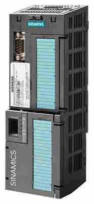
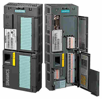
CU230P‑2 PN Control Unit
The Control Unit performs closed-loop control functions for the inverter.
The CU230P-2 Control Units are designed for drives with integrated technological functions for pump, fan and compressor applications.
The I/O interface, the fieldbus interfaces and the additional software functions optimally support these applications. The integration of technological functions is a significant differentiating feature to the other Control Units of the SINAMICS G120 drive family.
The CU230P-2 Control Units can be operated with the following Power Modules:
PM240‑2
PM240
PM250
Note:
The CU230P‑2 is the Control Unit for SINAMICS G120P and SINAMICS G120P Cabinet for pumps, fans and compressors.
Please refer to Catalog D 35 for more information.
Note:
Shield plates and shield connection kits are available. These can be used in the wiring installation for the Control Units and Power Modules to ensure that it complies with EMC guidelines.
For more information about shield connection kits and shield plates for Control Units and Power Modules, please refer to section "Supplementary system components".
Typical, integrated HVAC/HLK functions
Linear and quadratic torque characteristic for fluid flow and positive displacement machines
ECO mode for additional energy saving in U/f control mode
2 analog inputs (current/voltage can be selected) to directly connect pressure/level sensors
2 additional analog inputs to connect Pt1000/LG‑Ni1000 temperature sensors
Direct control of valves and flaps using two 230 V AC relays
Automatic restart
Flying restart
Skip frequencies
Hibernation mode
Load check function to monitor belts and flow
Cascade connection
4 integrated PID controllers (e.g. for temperature, pressure, air quality, level)
Multi-zone controller
Essential service mode
Real time clock with three time generators
IOP wizards for special applications
Pumps: Positive displacement (constant load torque) and centrifugal pumps (square load torque) with and without PID controller
Fans: Radial and axial fans (square load torque) with and without PID controller
Compressors: Positive displacement (constant load torque) and fluid flow machines (square load torque) with and without PID controller
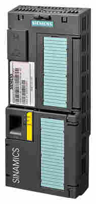
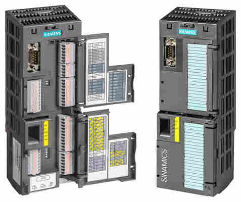
CU240E‑2 DP‑F Control Unit
The Control Unit performs closed-loop control functions for the inverter.
The CU240E‑2 Control Unit is designed as standard Control Unit for all of the usual applications involving U/f or vector control.
CU240E-2 series with standard I/O quantity structure and integrated safety technology
The CU240E‑2 Control Unit can be combined with the following Power Modules:
PM240‑2
PM240
PM250
Note:
Shield plates and shield connection kits are available. These can be used in the wiring installation for the Control Units and Power Modules to ensure that it complies with EMC guidelines.
For more information about shield connection kits and shield plates for Control Units and Power Modules, please refer to section "Supplementary system components".
Safety Integrated functions
The safety function "Safe Torque Off" (STO) (certified according to IEC 61508 SIL 2 and EN ISO 13849‑1 PL d and Category 3) is already integrated into the basic versions of the CU240E‑2 series (CU240E‑2, CU240E‑2 DP, CU240E‑2 PN).
With the fail-safe variants of the CU240E-2 series (CU240E‑2 F, CU240E‑2 DP-F, CU240E‑2 PN-F), the fail-safe SINAMICS G120 inverter provides five safety functions which are certified according to IEC 61508 SIL 2 and EN ISO 13849‑1 PL d and Category 3:
Safe Torque Off (STO)
to protect against active movement of the drive
Safe Stop 1 (SS1)
for continuous monitoring of a safe braking ramp
Safely Limited Speed (SLS)
for protection against dangerous movements when a speed limit is exceeded (the CU240E‑2 DP‑F Control Unit has up to 4 selectable SLS limit values)
Safe Direction (SDI)
This function ensures that the drive can only rotate in the selected direction.
Safe Speed Monitor (SSM)
This function signals if a drive operates below a specific speed/feed velocity (only CU240E‑2 DP‑F / CU240E‑2 PN‑F with PROFIsafe).
These functions can be activated by means of PROFIsafe or via the safety inputs.
None of the safety functions require a motor encoder and they are thus much cheaper and easier to implement. Existing systems in particular can be simply updated with safety technology without the need to change the motor or mechanical system.
The Safe Torque Off (STO) function can be used without restriction for all applications. The SS1, SLS, SDI and SSM functions are only permissible for applications where the load can never accelerate when the inverter is switched off. They are therefore not permitted for applications involving pull-through loads such as hoisting gear and unwinders.
Additional information is provided in chapter Highlights, section Safety Integrated.
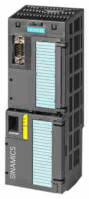
CU250S-2 Control Unit
The Control Unit performs closed-loop control functions for the inverter.
The CU250S‑2 Control Units are designed as standard Control Units for all of the usual applications involving V/f or vector control.
CU250S‑2 Control Units can be used to implement all common applications involving V/f or vector control as well as applications for drives with positioning requirements. This expansion allows them to be used in lifting, swiveling, traversing or rotating applications. The positioning functionality is comparable with SINAMICS S110 servo drives.
Two points must be noted here:
Vector control (VC) and sensorless vector control (SLVC) are possible
Positioning possible via one encoder or in parallel using two encoders
The CU250S‑2 Control Units can be combined with the following Power Modules:
PM240‑2
PM240
PM250
Note:
Shield plates and shield connection kits are available for use in the wiring installation of Control Units and Power Modules to ensure that it complies with EMC guidelines.
For more information about shield connection kits and shield plates for Control Units and Power Modules, please refer to section "Supplementary system components".
Safety Integrated functions
The following Safety Integrated Basic Functions (certified according to IEC 61508 SIL 2 and EN ISO 13849‑1 PL d and Category 3) are integrated as standard in the CU250S-2 series:
Safe Torque Off (STO)
to protect against active movement of the drive
Safe Stop 1 (SS1)
for continuous monitoring of a safe braking ramp
Safe Brake Control (SBC) is used to safely control a holding
brake
The following Safety Integrated Extended Functions (certified according to IEC 61508 SIL 2 and EN ISO 13849‑1 PL d and Category 3) are optionally available for the CU250S-2 series:
Safely Limited Speed (SLS)
for protection against dangerous movements on exceeding a speed limit
Safe Direction (SDI)
This function ensures that the drive can only rotate in the selected direction.
Safe Speed Monitor (SSM)
This function signals if a drive operates below a specific speed/feed velocity.
These functions can be activated by means of PROFIsafe or via the safety inputs.
None of the safety functions require a motor encoder and they are thus much cheaper and easier to implement. Existing systems in particular can be simply updated with safety technology without the need to change the motor or mechanical system.
The Safe Torque Off (STO) function can be used without restriction for all applications. The SS1, SLS, SDI and SSM functions are only permissible for applications where the load can never accelerate when the inverter is switched off. They are therefore not permitted for applications involving pull-through loads such as hoisting gear and unwinders.
Additional information is provided in chapter Highlights, section Safety Integrated.

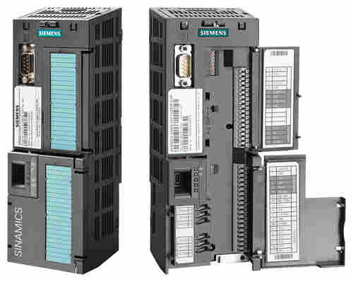
CU230P‑2 Control Unit with open and closed terminal covers
Terminal No. | Signal | Features |
|---|---|---|
Digital inputs (DI) – Standard | ||
69 | DI COM | Reference potential for digital inputs |
5 ... 8, | DI0 … DI5 | Freely programmable |
Digital outputs (DO) | ||
18 | DO0, NC | Relay output 1 |
19 | DO0, NO | Relay output 1 |
20 | DO0, COM | Relay output 1 |
21 | DO1, NO | Relay output 2 |
22 | DO1, COM | Relay output 2 |
23 | DO2, NC | Relay output 3 |
24 | DO2, NO | Relay output 3 |
25 | DO2, COM | Relay output 3 |
Analog inputs (AI) | ||
3 | AI0+ | Differential input, switchable between current, voltage |
4 | AI0- | |
10 | AI1+ | Differential input, switchable between current, voltage |
11 | AI1- | |
50 | AI2+ | Non-isolated input, switchable between current and temperature sensors, type Pt1000/LG-Ni1000 |
51 | GND | Reference potential of the AI2/internal electronics ground |
52 | AI3+ | Non-isolated input for temperature sensors, type Pt1000/LG‑Ni1000 |
53 | GND | Reference potential of the AI3/internal electronics ground |
Analog outputs (AO) | ||
12 | AO0+ | Non-isolated output |
13 | GND | Reference potential of the AO0/internal electronics ground |
26 | AO1+ | Non-isolated output |
27 | GND | Reference potential of the AO1/internal electronics ground |
PTC/KTY interface | ||
14 | T1 MOTOR | Positive input for motor temperature sensor |
15 | T2 MOTOR | Negative input for motor temperature sensor |
Power supply | ||
9 | +24 V OUT | Power supply output |
28 | GND | Reference potential of the power supply/internal electronics ground |
1 | +10 V OUT | Power supply output |
2 | GND | Reference potential of the power supply/internal electronics ground |
31 | +24 V IN | Power supply input |
32 | GND IN | Reference potential of the power supply input |
35 | +10 V OUT | Power supply output |
36 | GND | Reference potential of the power supply/internal electronics ground |
1) The following applies to systems complying with UL: A maximum of 3 A, 30 V DC or 2 A, 250 V AC may be connected via terminals 18 / 20 (DO0 NC) and 23 / 25 (DO2 NC).
CU240E‑2 Control Unit with open and closed terminal covers
Terminal No. | Signal | Features |
|---|---|---|
Digital inputs (DI) – Standard | ||
5 ... 8, | DI0 … DI5 | Freely programmable (isolated) 5.5 mA/24 V |
69 | DI COM1 | Reference potential for digital inputs |
34 | DI COM2 | Reference potential for digital inputs |
Digital inputs (DI) – Fail-safe | ||
16, 17 | F-DI0 | Fail-safe digital inputs, 2 channels (redundant), |
The following are only available for CU240E‑2 F, CU240E‑2 DP‑F and CU240E‑2 PN‑F | ||
5, 6 | F-DI0 | Fail-safe digital inputs, 2 channels (redundant), |
7, 8 | F-DI1 | Fail-safe digital inputs, 2 channels (redundant), |
16, 17 | F-DI2 | Fail-safe digital inputs, 2 channels (redundant), |
Digital outputs (DO) | ||
18 | DO0, NC | Relay output DO0 |
19 | DO0, NO | Relay output DO0 |
20 | DO0, COM | Relay output DO0 |
21 | DO1+ | Transistor output DO1 |
22 | DO1- | Transistor output DO1 |
23 | DO2, NC | Relay output DO2 |
24 | DO2, NO | Relay output DO2 |
25 | DO2, COM | Relay output DO2 |
Analog inputs (AI) | ||
3 | AI0+ | Differential input, switchable between current, voltage |
4 | AI0- | |
10 | AI1+ | Differential input, switchable between current, voltage |
11 | AI1- | |
Analog outputs (AO) | ||
12 | AO0+ | Non-isolated output |
13 | GND | Reference potential of the AO0/internal electronics ground |
26 | AO1+ | Non-isolated output |
27 | GND | Reference potential of the AO1/internal electronics ground |
PTC/KTY interface | ||
14 | T1 MOTOR | Positive input for motor temperature sensor |
15 | T2 MOTOR | Negative input for motor temperature sensor |
Power supply | ||
9 | +24 V OUT | Power supply output |
28 | GND | Reference potential of the power supply/internal electronics ground |
1 | +10 V OUT | Power supply output |
2 | GND | Reference potential of the power supply/internal electronics ground |
31 | +24 V IN | Power supply input |
32 | GND IN | Reference potential of the power supply input |
CU250S-2 Control Unit with open and closed terminal covers
Terminal No. | Signal | Features |
|---|---|---|
Digital inputs (DI) | ||
5 | DI0 | Digital inputs, floating, 5.5 mA/24 V |
6 | DI1+ | Digital inputs, floating, 5.5 mA/24 V |
64 | DI1- | Digital inputs, floating, 5.5 mA/24 V |
7 | DI2 | Digital inputs, floating, 5.5 mA/24 V |
8 | DI3+ | Digital inputs, floating, 5.5 mA/24 V |
65 | DI3- | Digital inputs, floating, 5.5 mA/24 V |
16 | DI4 | Digital inputs, floating, 5.5 mA/24 V |
17 | DI5+ | Digital inputs, floating, 5.5 mA/24 V |
66 | DI5- | Digital inputs, floating, 5.5 mA/24 V |
67 | DI6 | Digital inputs, floating, 5.5 mA/24 V |
69 | DI COM1 | Reference potential for digital inputs DI0, DI2, DI4, DI6 |
Digital inputs (DI) | ||
41 ... 44 | DI16 ... DI19 | Freely programmable (isolated) 5.5 mA/24 V |
40 | DI COM3 | Reference potential for digital inputs DI16 ... DI19 |
Digital inputs (DI) – Fail-safe | ||
5, 6 | F-DI0 | Fail-safe digital inputs, 2 channels (redundant), |
7, 8 | F-DI1 | Fail-safe digital inputs, 2 channels (redundant), |
16, 17 | F-DI2 | Fail-safe digital inputs, 2 channels (redundant), |
69 | DI COM1 | Reference potential for digital inputs F-DI0, F-DI1, F-DI2 |
Switchable digital inputs or outputs (digital inputs DI24 to DI27can also be used as a pulse input with a maximum frequency of 32 kHz) | ||
51 | DI24/DO24 | Freely programmable (non-floating), DI: 5.5 mA/24 V, DO: 100 mA/24 V |
53 | DI25/DO25 | Freely programmable (non-floating), DI: 5.5 mA/24 V, DO: 100 mA/24 V |
53 | DI26/DO26 | Freely programmable (non-floating), DI: 5.5 mA/24 V, DO: 100 mA/24 V |
54 | DI27/DO27 | Freely programmable (non-floating), DI: 5.5 mA/24 V, DO: 100 mA/24 V |
50 | GND | Reference potential |
Digital outputs (DO) – Fail-safe | ||
18 | DO0, NC | Relay output DO0 |
19 | DO0, NO | Relay output DO0 |
20 | DO0, COM | Relay output DO0 |
21 | DO1 NO | Transistor output DO1 |
22 | DO1 COM | Transistor output DO1 |
23 | DO2, NC | Relay output DO2 |
24 | DO2, NO | Relay output DO2 |
25 | DO2, COM | Relay output DO2 |
Analog inputs (AI) | ||
3 | AI0+ | Differential input, switchable between current, voltage |
4 | AI0- | |
10 | AI1+ | Differential input, switchable between current, voltage |
11 | AI1- | |
13 | GND | Reference potential of AI |
Analog outputs (AO) | ||
12 | AO0+ | Non-isolated output |
26 | AO1+ | Non-isolated output |
27 | GND | Reference potential of AO |
PTC/KTY interface | ||
14 | T1 MOTOR | Positive input for motor temperature sensor |
15 | T2 MOTOR | Negative input for motor temperature sensor |
Power supply | ||
9 | +24 V OUT | Power supply output |
6XV14404AN25
6XV14404BH20
6XV14404BH50
6XV14404BH80
6XV14404BN10
6XV14404BN15
6XV14404BN20
6XV14404BN25
6AV66715AE000AX0
6AV66715AE010AX0
6AV66715AE100AX0
6AV66715AE110AX0
6AV65741AF044AA0
6AV66715AD000AX0
6AV66715CL000AX0
6AV66715CE000AX1
6AV66715CM000AX1
6AV66410CA010AX1
6AV66420BA011AX1
6AV66420BC011AX1
6AV66420BD013AX0
6AV66420DA011AX1
6AV66420DC011AX1
6AV66420EA013AX0
6AV66425EA100CG0
6AV66428BA100AA0
6AV66430AA011AX0
6AV66430BA011AX0
6AV66430CB011AX1
6AV66430CD011AX1
6AV66430DB011AX1
6AV66430DD011AX1
6AV66430ED012AX0
6AV66440AA012AX0
6AV66440AB012AX0
6AV66440AC012AX1
6AV66440BA012AX1
6AV66440CB012AX0
6AV66442AB012AX0
6AV66448AB200AA1
6AV63812BC074AV0
6AV63812BD074AV0
6AV63812BE074AV0
6AV63812BH074AV0
6AV63812BF074AV0
6AV63812BJ074AV0
6AV63812BK074AV0
6AV63812BL074AV0
6AV63812BM074AV0
6AV63812BN074AV0
6AV63812BP074AV0
6AV63812BS074AV0
6AV63812BQ074AV0
6AV63812BT074AV0
6AV63812BU074AV0
6AV63812BV074AV0
6AV63711CA074AX0
6AV63711CF074AX0
6AV63621AB000BB0
6AV63621AD000BB0
6AV63621AF000BB0
6AV63621AJ000BB0
6AV63621AM000BB0
6AV63623AB000BB0
6AV63623AD000BB0
6AV63623AF000BB0
6AV63623AJ000BB0
6AV63622AB000BB0
6AV63622AD000BB0
6AV63622AF000BB0
6AV63622AJ000BB0
6AV63622AM000BB0
6AV63622BB000BB0
6AV63622BD000BB0
6AV63622BF000BB0
6AV63622BJ000BB0
6AV63622BM000BB0
6AV63711DQ174AX0
6AV63711DQ174BX0
6AV63711DQ174CX0
6AV63711DQ174EX0
6AV63621BA000BB0
6AV63621FA000BB0
6AV63711CB074AX0
6AV63711CC074AX0
6AV63711DR074AX0
6AV63711DR174AX0
6AV63624AA074AA0
6AV63624AD000BB0
6AV63624AF000BB0
6AV63624AH000BB0
6AV63721DC074AX0
6AV63721DD074AX0
6AV63711DG074AX0
6AV63711DV074AX0
6AV63711DV174AX0
6AV63711DV274AX0
6AV63722DG074AA0
6AV63722CG200BA0
6AV63722CG200CA0
6AV63722CG200DA0
6AV63722CG200EA0
6AV63712BD074AX0
6AV63712BG074AX0
6AV63712BM074AX0
6AV63712BN074AX0
6AV63712BP074AX0
6AV63712BQ074AX0
6AV63712BR074AX0
6AV63712BD174AX0
6AV63712BG174AX0
6AV63712BM174AX0
6AV63712BN174AX0
6AV63712BP174AX0
6AV63712BQ174AX0
6AV63712BR174AX0
6AV63812AA074AV3
6AV63812AB074AV3
6AV63812BC074AX0
6AV63812BD074AX0
